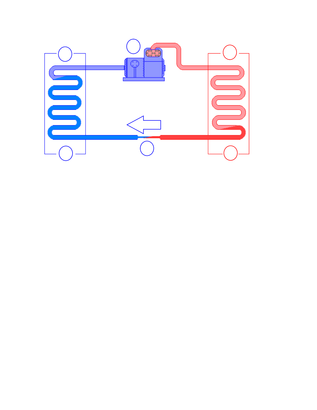
VAPOR / COMPRESSION REFRIGERATION CYCLE
In the vapor / compression refrigeration cycle, liquid refrigerant at a high pressure is delivered to a metering
device, (
1
). The metering device causes a reduction in pressure, and therefore a reduction in saturation temperature.
The refrigerant then travels to the evaporator, (
2
). Heat is absorbed in the evaporator and causes the refrigerant
to boil from liquid to vapor. At the outlet of the evaporator, (
3
), the refrigerant is now a low temperature, low
pressure vapor. The refrigerant vapor then travels to the inlet of the compressor, (
4
). The refrigerant vapor is
then compressed and moves to the condenser, (
5
). The refrigerant is now a high temperature, high pressure va‐
por. As the refrigerant expels heat, the refrigerant condenses to a liquid. At the condenser outlet, (
6
), the refrig‐
erant is a high pressure liquid. The high pressure liquid refrigerant is delivered to the metering device, (
1
), and
the sequence begins again.
Some accessories that are not shown in the basic diagram are the receiver and accumulator. Use of these compo‐
nents depends on system design and / or on the type of metering device used. A system that uses a thermostatic
expansion valve is usually equipped with a receiver, which would be located in the liquid line directly follow‐
ing the condenser. A system that uses a capillary tube or fixed bore metering device is usually equipped
with an accumulator, which would be located in the suction line directly following the evaporator.
ii
1
2
3
4
5
6
Flow


